
Page 20 - Computer_Science_F5
P. 20
Chapter One: Computer architecture
OR: This is like connecting two switches in parallel. The light is on (TRUE)
if either switch (or both) is turned on (TRUE). Figure 1.10 illustrate the idea.
SW1
FOR ONLINE READING ONLY
+3V
Parallel switches SW2
Figure 1.10: Connecting two switches in parallel
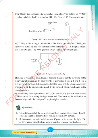
NOT: This is like a single switch with a flip. If the switch is on (TRUE), the
light is off (FALSE), and vice versa as shown in Figure 1.11. In a digital circuit,
this is a NOT gate, The NOT gate is a single input single output gate.
Voltage
source A L
Figure 1.11: A single switch with a flip
This gate is referred to as an Inverter because it carries out the inversion of the
binary signal it receives. In other words, it converts a 0 into a 1 or a 1 into a
0. The switching circuit demonstrates that the lamp will be illuminated when
switch A is in the open position and it will turn off when switch A is in the
closed position.
By combining these operations (AND, OR, and NOT), you can create more
complex rules for turning the light on or off. This mirrors the utilisation of
Boolean algebra in the design of complex digital circuits.
Questions:
1. Using the context of the scenario explain how can you achieve your desired
outcome (light or dark) without turning a switch ON or OFF.
2. Reflect on the scenario and determine if your choice to turn the light ON
or OFF aligns with Boolean logic principles. Discuss your findings.
11
Student’s Book Form Five
Computer Science Form 5.indd 11 23/07/2024 12:32