
Page 47 - Physics_Form_2
P. 47
Current electricity
difference (p.d) is the work done in Measurement of the e.m.f of a cell and
moving a unit charge in a circuit from one the p.d across a conductor
point to another. Potential difference (p.d) The e.m.f. of a cell and p.d are measured
is also called voltage. using a high resistance device called
work done(W) a voltmeter. A voltmeter measures the
p.d (V)=
FOR ONLINE READING ONLY
charge(Q) difference in potential between two
points. It is always connected in parallel
with the cell or the load because the e.m.f.
Like the e.m.f., the SI unit for p.d is the volt
(V). One volt is equivalent to one joule of a cell is compared to the p.d across
per coulomb. Figure 2.2 shows a circuit the voltmeter’s terminals. To measure
diagram with the dashed box indicating e.m.f. and p.d, the positive terminal of
a region where the potential difference the voltmeter is connected to the positive
between two points of a resistor can be terminal of a cell, and the negative
measured. terminal of the voltmeter is connected to
the negative terminal of the cell. Note:
The difference between e.m.f. and p.d is Measuring e.m.f by a voltmeter only
that e.m.f is the potential difference across provides an estimated value, since a small
the cell terminals when no current flows amount of current is drawn by the meter
or no load is connected. In contrast, p.d contrary to the requirement that no current
is measured when current flows through is drawn for e.m.f measurement. Activity
the circuit or when a load is connected. 2.1 will assist on understanding how
The load here refers to the resistance, R, one can measure of a cell and potential
of the electrical appliance connected to difference of a conductor.
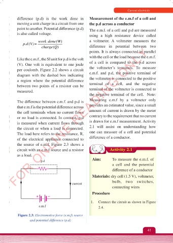
the source of e.m.f. Figure 2.3 shows a
circuit with an e.m.f source and a resistor Activity 2.1
as a load.
p.d Aim: To measure the e.m.f. of
a cell and the potential
difference of a conductor
Materials: dry cell (1.5 V), voltmeter,
bulb, two switches,
current
connecting wires
Procedure
1. Connect the circuit as shown in Figure
e.m.f 2.4.
Figure 2.3: Electromotive force (e.m.f) source
and potential difference (p.d)
41
Physics Form 2 Final.indd 41 25/10/2025 10:25