
Page 48 - Physics_Form_2
P. 48
Physics for Secondary Schools
Electric circuits and symbols
Circuit diagrams are visual representations
of electrical circuits, using circuit symbols
to represent electrical components and their
connections. You can create these diagrams
S by placing components and connecting
FOR ONLINE READING ONLY
E 1
them with lines. These diagrams are
crucial for understanding and building
electrical circuits. Various IT tools, such
S as virtual labs and Smart Draw, may assist
Bulb 2
in developing the skills to construct an
Figure 2.4 electric circuit.
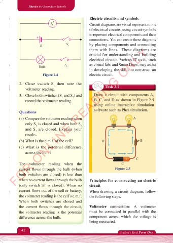
2. Close switch S then note the
1,
voltmeter reading. Task 2.1
3. Close both switches (S and S ) and Draw a circuit with components A,
2
1
record the voltmeter reading. B, C, and D as shown in Figure 2.5
using online interactive simulation
Questions software such as Phet simulation.
(a) Compare the voltmeter reading when A
only S is closed and when both S
1
1
and S are closed. Explain your
2
results.
(b) What is the e.m.f. of the cell? D B
(c) What is the potential difference
across the bulb?
C
The voltmeter reading when the C
current flows through the bulb (when Figure 2.5
both switches are closed) is less than
when no current flows through the bulb Principles for constructing an electric
(only switch S1 is closed). When no circuit
current flows out of the cell or battery, When drawing a circuit diagram, follow
the voltmeter reading is the cell’s e.m.f. the following steps.
When both switches are closed and
the current flows through the circuit, Voltmeter connection: A voltmeter
the voltmeter reading is the potential must be connected in parallel with the
difference across the bulb. component across which the voltage is
being measured.
42
Student’s Book Form One
Physics Form 2 Final.indd 42 25/10/2025 10:25