
Page 30 - Computer_Science_F5
P. 30
Logic gates
A logic gate is an electronic circuit that involves two or more binary input signals
and one binary output signal. These gates are critical when dealing with electronics. Chapter One: Computer architecture
They are used to construct the digital system. The logic gates can perform the logic
operation in single or multiple binary inputs and give one binary output. Logic gates
FOR ONLINE READING ONLY
are considered as a single unit; however, gates comprise one or more transistors.
Standard logic gates symbols
The basic logic gates include OR, AND, NOT, NAND, NOR and XOR gates. The
NOT gate has only one input signal and one output signal while other gates have
two or more input signals. The standard logic gates symbols and operation of each
logic gate are as follows:
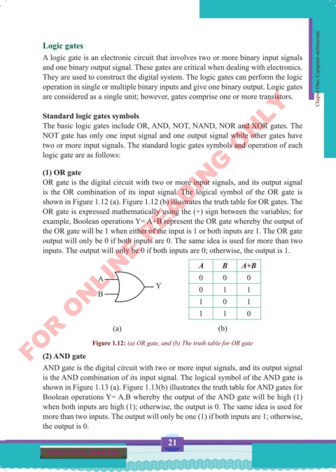
(1) OR gate
OR gate is the digital circuit with two or more input signals, and its output signal
is the OR combination of its input signal. The logical symbol of the OR gate is
shown in Figure 1.12 (a). Figure 1.12 (b) illustrates the truth table for OR gates. The
OR gate is expressed mathematically using the (+) sign between the variables; for
example, Boolean operations Y= A+B represent the OR gate whereby the output of
the OR gate will be 1 when either of the input is 1 or both inputs are 1. The OR gate
output will only be 0 if both inputs are 0. The same idea is used for more than two
inputs. The output will only be 0 if both inputs are 0; otherwise, the output is 1.
A B A+B
A 0 0 0
Y 0 1 1
B
1 0 1
1 1 0
(a) (b)
Figure 1.12: (a) OR gate, and (b) The truth table for OR gate
(2) AND gate
AND gate is the digital circuit with two or more input signals, and its output signal
is the AND combination of its input signal. The logical symbol of the AND gate is
shown in Figure 1.13 (a). Figure 1.13(b) illustrates the truth table for AND gates for
Boolean operations Y= A.B whereby the output of the AND gate will be high (1)
when both inputs are high (1); otherwise, the output is 0. The same idea is used for
more than two inputs. The output will only be one (1) if both inputs are 1; otherwise,
the output is 0.
21
Student’s Book Form Five
Computer Science Form 5.indd 21 23/07/2024 12:32