Page 32 - Computer_Science_F5
P. 32

Note: Using DeMorgan’s theorem, you can create other gates from basic gates. For
                    example, the NAND gate is the same as the OR gate with inverted inputs as
                    shown in Figure 1.16.                                                          Chapter One: Computer architecture


                          A
          FOR ONLINE READING ONLY
                                        Y                 A
                          B                                                Y
                                                          B

                                     (a)                            (b)
                           Figure 1.16: (a) NAND gate, and (b) OR gate with inverted inputs
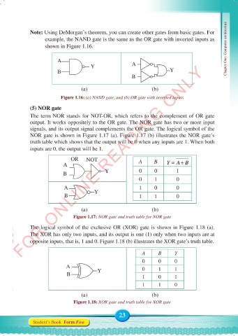
              (5) NOR gate
              The term NOR stands for NOT-OR, which refers to the complement of OR gate
              output. It works oppositely to the OR gate. The NOR gate has two or more input
              signals, and its output signal complements the OR gate. The logical symbol of the
              NOR gate is shown in Figure 1.17 (a). Figure 1.17 (b) illustrates the NOR gate’s
              truth table which shows that the output will be 0 when any inputs are 1. When both
              inputs are 0, the output will be 1.

                                OR    NOT                    A      B
                            A                                            Y = A+ B
                            B                 Y              0      0        1
                                                             0      1        0

                             A                               1      0        0
                             B            Y                  1      1        0


                                     (a)                            (b)
                                 Figure 1.17: NOR gate and truth table for NOR gate
              The logical symbol of the exclusive OR (XOR) gate is shown in Figure 1.18 (a).
              The XOR has only two inputs, and its output is one (1) only when two inputs are at
              opposite inputs, that is, 1 and 0. Figure 1.18 (b) illustrates the XOR gate’s truth table.

                                                               A      B      Y

                                                               0      0      0
                              A                                0      1      1
                              B            Y                   1      0      1

                                                               1      1      0
                                     (a)                            (b)

                                 Figure 1.18: XOR gate and truth table for XOR gate

                                                     23
               Student’s Book  Form Five


     Computer Science Form 5.indd   23                                                      23/07/2024   12:32
   27   28   29   30   31   32   33   34   35   36   37