
Page 34 - Computer_Science_F5
P. 34
Chapter One: Computer architecture
FOR ONLINE READING ONLY
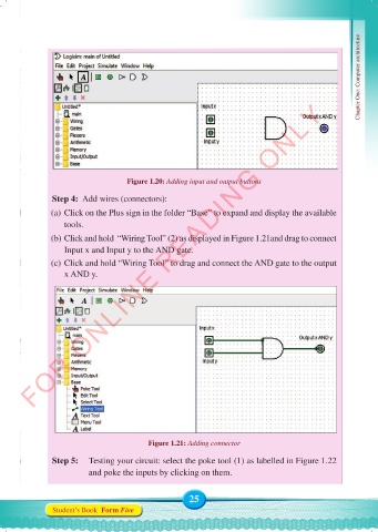
Figure 1.20: Adding input and output buttons
Step 4: Add wires (connectors):
(a) Click on the Plus sign in the folder “Base” to expand and display the available
tools.
(b) Click and hold “Wiring Tool” (2) as displayed in Figure 1.21and drag to connect
Input x and Input y to the AND gate.
(c) Click and hold “Wiring Tool” to drag and connect the AND gate to the output
x AND y.
Figure 1.21: Adding connector
Step 5: Testing your circuit: select the poke tool (1) as labelled in Figure 1.22
and poke the inputs by clicking on them.
25
Student’s Book Form Five
Computer Science Form 5.indd 25 23/07/2024 12:32