
Page 31 - Computer_Science_F5
P. 31
Computer Science A Y A B A.B
0
0
0
1
0
0
B
1
0
0
FOR ONLINE READING ONLY
1
(a) 1 (b) 1
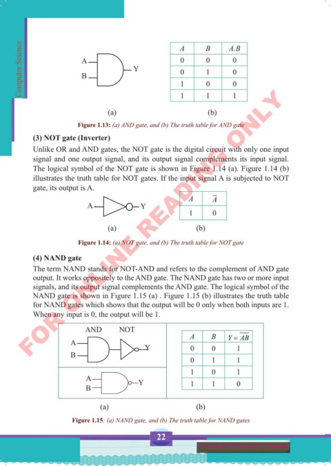
Figure 1.13: (a) AND gate, and (b) The truth table for AND gate
(3) NOT gate (Inverter)
Unlike OR and AND gates, the NOT gate is the digital circuit with only one input
signal and one output signal, and its output signal complements its input signal.
The logical symbol of the NOT gate is shown in Figure 1.14 (a). Figure 1.14 (b)
illustrates the truth table for NOT gates. If the input signal A is subjected to NOT
gate, its output is A.
A A
A Y
1 0
(a) (b)
Figure 1.14: (a) NOT gate, and (b) The truth table for NOT gate
(4) NAND gate
The term NAND stands for NOT-AND and refers to the complement of AND gate
output. It works oppositely to the AND gate. The NAND gate has two or more input
signals, and its output signal complements the AND gate. The logical symbol of the
NAND gate is shown in Figure 1.15 (a) . Figure 1.15 (b) illustrates the truth table
for NAND gates which shows that the output will be 0 only when both inputs are 1.
When any input is 0, the output will be 1.
AND NOT
A B Y = AB
A Y 0 0 1
B
0 1 1
1 0 1
A Y
B 1 1 0
(a) (b)
Figure 1.15: (a) NAND gate, and (b) The truth table for NAND gates
22
for Advanced Secondary Schools
Computer Science Form 5.indd 22 23/07/2024 12:32