
Page 32 - Physics_Form_2
P. 32
Physics for Secondary Schools
resistor. Figure 1.34 shows a circuit used Therefore,
for discharging a capacitor.
I = CV
t
Construction of an air-filled capacitor
V
FOR ONLINE READING ONLY
I I Project 1.2
In groups, construct an air-filled
capacitor. Note that any arrangement
Figure 1.34: Discharging a capacitor of two parallel conductors, such as
metal plates placed close together but
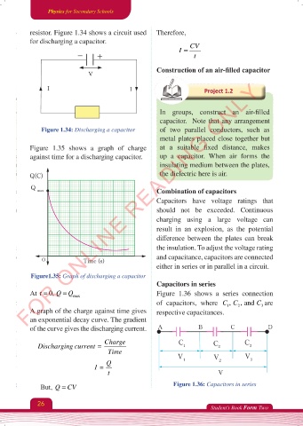
Figure 1.35 shows a graph of charge at a suitable fixed distance, makes
against time for a discharging capacitor. up a capacitor. When air forms the
insulating medium between the plates,
the dielectric here is air.
Q(C)
Q
max Combination of capacitors
Capacitors have voltage ratings that
should not be exceeded. Continuous
charging using a large voltage can
result in an explosion, as the potential
difference between the plates can break
the insulation. To adjust the voltage rating
and capacitance, capacitors are connected
O Time (s)
either in series or in parallel in a circuit.
Figure1.35: Graph of discharging a capacitor
Capacitors in series
At t = 0, QQ= max Figure 1.36 shows a series connection
,
of capacitors, where CC 2 , and C are
1
3
A graph of the charge against time gives respective capacitances.
an exponential decay curve. The gradient
of the curve gives the discharging current. A B C D
Charge C C
Discharging current = 1 C 2 3
Time
V V V
Q 1 2 3
I=
t V
But, Q CV= Figure 1.36: Capacitors in series
26
Student’s Book Form Two
Physics Form 2 Final.indd 26 25/10/2025 10:25