
Page 73 - Computer_Science_F5
P. 73
Computer Science (e) Write back
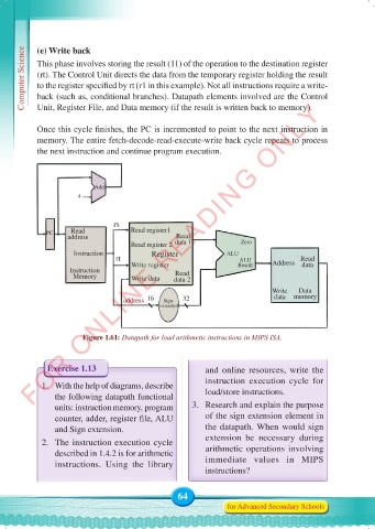
This phase involves storing the result (11) of the operation to the destination register
(rt). The Control Unit directs the data from the temporary register holding the result
to the register specified by rt (r1 in this example). Not all instructions require a write-
back (such as, conditional branches). Datapath elements involved are the Control
FOR ONLINE READING ONLY
Unit, Register File, and Data memory (if the result is written back to memory).
Once this cycle finishes, the PC is incremented to point to the next instruction in
memory. The entire fetch-decode-read-execute-write back cycle repeats to process
the next instruction and continue program execution.
Add
4
rs
PC Read Read register1
address Read
Read register 2 data 1 Zero
Instruction Register ALU
rt ALU Read
Write register Result Address data
Instruction Read
Memory Write data data 2
Write Data
address 16 Sign- 32 data memory
extended
Figure 1.61: Datapath for load arithmetic instructions in MIPS ISA.
Exercise 1.13 and online resources, write the
instruction execution cycle for
1. With the help of diagrams, describe
the following datapath functional load/store instructions.
units: instruction memory, program 3. Research and explain the purpose
counter, adder, register file, ALU of the sign extension element in
and Sign extension. the datapath. When would sign
2. The instruction execution cycle extension be necessary during
described in 1.4.2 is for arithmetic arithmetic operations involving
instructions. Using the library immediate values in MIPS
instructions?
64
for Advanced Secondary Schools
Computer Science Form 5.indd 64 23/07/2024 12:32