
Page 201 - Physics_Form_2
P. 201
Refraction and dispersion of light
Other common terms used are; real image, virtual image, image distance, v, object
distance, u and magnification, m. All these terms take the same meaning as they were
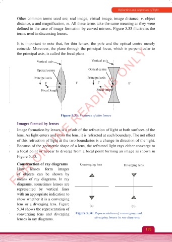
defined in the case of image formation by curved mirrors. Figure 5.33 illustrates the
terms used in discussing lenses.
It is important to note that, for thin lenses, the pole and the optical centre merely
FOR ONLINE READING ONLY
coincide. Moreover, the plane through the principal focus, which is perpendicular to
the principal axis, is called the focal plane.
Vertical axis Vertical axis
Optical centre Optical centre
Principal axis Principal axis
F F F F
Focal length Focal length
Figure 5.33: Features of thin lenses
Images formed by lenses
Image formation by lenses is a result of the refraction of light at both surfaces of the
lens. As light enters and exits the lens, it is refracted at each boundary. The net effect
of this refraction of light at the two boundaries is a change in direction of the light.
Because of the geometric shape of a lens, the refracted light rays either converge to
a focal point or appear to diverge from a focal point forming an image as shown in
Figure 5.30.
Construction of ray diagrams Converging lens Diverging lens
How lenses form images
of objects can be shown by
means of ray diagrams. In ray
diagrams, sometimes lenses are
represented by vertical lines
with an appropriate indication to
show whether it is a converging
lens or a diverging lens. Figure (a) (b)
5.34 shows the representation of
converging lens and diverging Figure 5.34: Representation of converging and
lenses in ray diagrams. diverging lenses in ray diagrams
195
Physics Form 2 Final.indd 195 25/10/2025 10:28