
Page 206 - Physics_Form_2
P. 206
Physics for Secondary Schools
lines, extend the refracted rays on the
distance between point 2F and the opposite side of the lens until they
1
optical centre, O. intersect. The point of intersection
3. Using the chosen scale, draw an is the image point of the top of the
upright arrow at a point just beyond object. Note that, any two rays are
2F . The arrow represents an object. enough to locate the position of an
1
FOR ONLINE READING ONLY
4. From the top of the object arrow, object.
draw a ray toward the focal point
on the opposite side of the lens, 7. Now, choose a point at the bottom
stopping at the lens. of the object and repeat steps 4
5. Draw a second ray parallel to to 7. This way you can locate the
the principal axis, and a third ray image of the bottom of the object.
directed to the optical center of the Use an arrow to draw the image by
lens, marking arrowheads to indicate joining the top and bottom points of
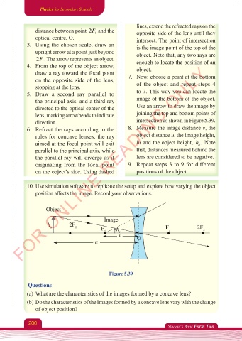
direction. intersection as shown in Figure 5.39.
6. Refract the rays according to the 8. Measure the image distance v, the
rules for concave lenses: the ray object distance u, the image height,
.
aimed at the focal point will exit hi and the object height, h Note
o
parallel to the principal axis, while that, distances measured behind the
the parallel ray will diverge as if lens are considered to be negative.
originating from the focal point 9. Repeat steps 3 to 9 for different
on the object’s side. Using dashed positions of the object.
10. Use simulation software to replicate the setup and explore how varying the object
position affects the image. Record your observations.
Object
Image
h 2F
o 1 F h F 2F
1 i 2 2
v O
u
Figure 5.39
Questions
(a) What are the characteristics of the images formed by a concave lens?
(b) Do the characteristics of the images formed by a concave lens vary with the change
of object position?
200
Student’s Book Form Two
Physics Form 2 Final.indd 200 25/10/2025 10:28